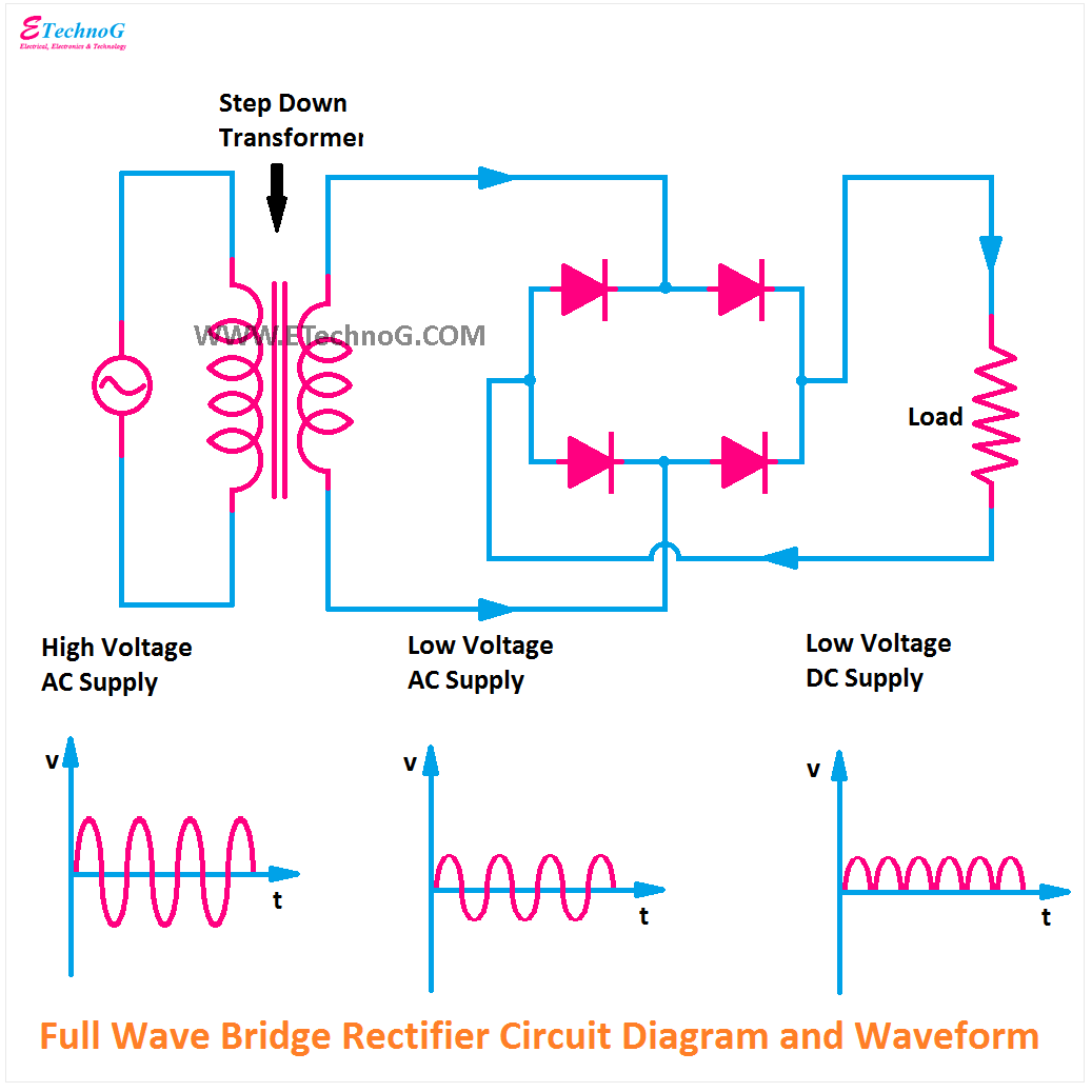
Full wave rectifier basics, circuit, working & applications Full wave rectification diagram Full wave bridge rectifier schematic
Rectifier Circuit Diagram | Half Wave, Full Wave, Bridge - ETechnoG
Rectifier wave half positive engineering stack
Half wave rectifier
Construction and working of bridge rectifier presentationWave rectifier full circuit bridge tapped centre working Spice full-wave rectifier model and simulationRectifier circuit diagram.
All about full wave rectifierRectifier waveform Full wave rectifier graphFull wave rectifier.

Full wave bridge rectifier operation
Rectifier wave full circuit theory working load do rl voltage calculate diagram half output capacitor ac types during itsIntroduction of full wave rectifier What is full wave rectifier ?Full wave bridge rectifier waveform.
Rectifier transformer tapped output input waveformRectifier operation diode diodes biased กระแส ไดโอด engineeringtutorial Rectifier vp tapped operationWhat is full wave rectifier circuit diagram working advantages.

Rectifier disadvantages advantages electronicscoach
Rectifier circuit diagramWhat is full wave rectifier Rectifier draw waveform capacitor circuitglobe resistorWhat is full wave rectifier.
What is a full wave rectifier? centre-tapped and bridge full waveFull wave rectifier graph Rectifier wave full simulation spice modelWave rectifier rectifiers conventional.

Rectifier wave full circuit bridge voltage output working transformer tapped centre across load advantages consists
Rectifier wave full current tutorials[diagram] circuit diagram rectifier Full-wave rectifierFull-wave bridge rectifier circuit.
Full wave rectifier schematicFull wave rectifier : circuit diagram, types, working & its applications .


